PITOBAR – Larger Pipe Sizes

, , ,

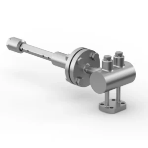
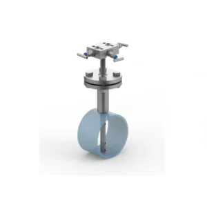
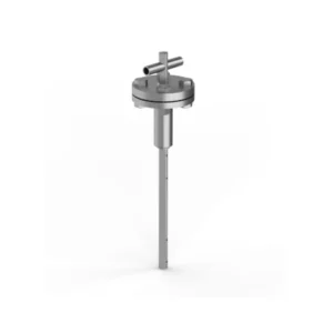
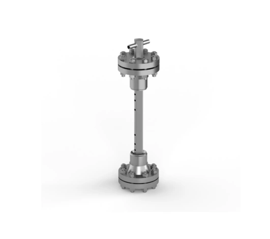
EMCO PITOBAR Averaging Pitot Tube for Larger Pipe Sizes (Type PC 450, PC455)
The PITOBAR Averaging Pitot Tube is used to measure the flow of liquid and gasses in horizontal or vertical pipe lines. Its working principle is derived from the classic or single point pitot tube. However, as opposed to the single point pitot tube, the PITOBAR Averaging Pitot Tube has a number of holes depending on pipe size pointing towards the upstream side. One port pointing downstream measures the static pressure. The main advantages of this flow element are its low installation costs and low pressure loss compared to other flow elements, especially in larger pipe sizes.

Download Documents

Design
The PITOBAR Averaging Pitot Tube is constructed and designed with a diamond shaped strut with several ports spaced centrally within concentric rings of equal area pointing towards the upstream side. This is done in order to get the best averaging measurement of the dynamic pressure, resulting in a more
accurate flow reading. The pitot tube creates a differential pressure signal which is proportional to the flow rate: Differential Pressure = ( Pstatic + Pdynamic) – Pstatic.

Installation
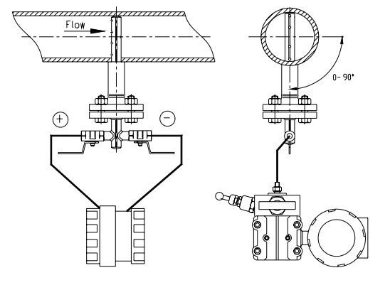
For optimal installation, the pitot tube should be placed in a straight cylindrical pipe with consistent cross-sectional area and free from obstructions. The inner pipe diameter must not deviate by more than 0.3% for accurate differential pressure calculations. To ensure accurate measurements, it is recommended to use full bore valves upstream of the primary element. The inner pipe wall roughness should meet specific limits depending on the material used. For steam flow, a horizontal mounting with a 5-degree slope is advised to facilitate condensate flow. Purge connections are available for fluids with impurities, and regular maintenance is suggested to maintain accurate readings. For proper instrument connection, the differential pressure transmitter should be positioned below the pitot tube for liquid and steam flow, and above it for gas flow, with impulse lines sloped to allow air escape.
  • Easy to install
  • Simple construction
  • Free choice for horizontal or vertical pipe run
  • Risk of leakage is minimized
  • Very low pressure loss
  • No moving parts

Construction

Design and calculation standards

VDE/VDI 2640, ASME, DIN, EN 13480

Types

PC450 & PC455

Pipe sizes

DN 500 – DN 6000: 20″ – 240″

Probe sizes

45 x 45 mm

Pressure rating

up to PN 100 (600lbs)

Temperature range

-100°C – +300 °C

Material PITOBAR

Stainless steel AISI 316, other stainless grades on request

Material mounting part

Carbon steel, stainless steel AISI 316, other on request

Process connection

Flange according to pressure rating

Flange standards

DIN, ANSI, others on request

Mounting

Welding to the pipe

Instrument connection

½” BSP or NPT

Technical Data

Accuracy

± 1% accuracy of actual flow

Repeatability

± 0,1%

Reynolds no.

Minimum 100.000 at full flow

Rangeability

10:1

Max. fluid velocity

Liquids 5 m/s, gasses 80 m/s

Accessories

Shut-off valves: needle or ball

Required Straight Pipe Lengths

Certain installation requirements for straight pipe lines must be fulfilled in order to achieve the most accurate flow measurement. See table below.

Upstream (x D)
Downstream (x D)
Single 90° bend
9
3
Two or more 90° bends in the same plane
14
3
Two or more 90° bends in in different planes
24
4

ต้องการใบเสนอราคา

Line add : @intech2000

Email : intech@intech2000.com

Phone : 02-440-1853

Scroll to Top