MEF

, , ,

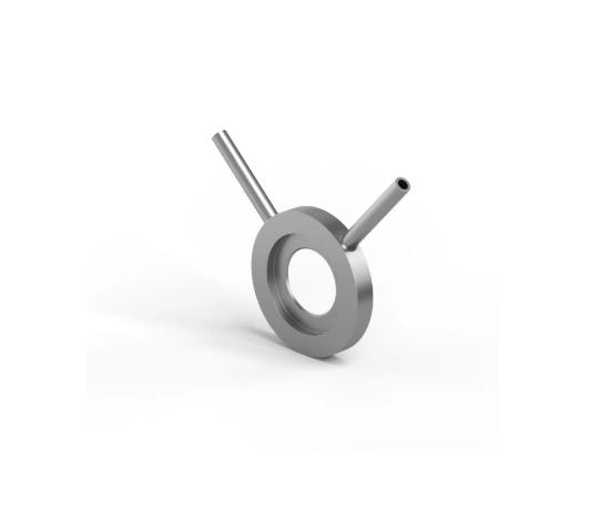
EMCO Orifice Plate Series MEF with Single Pressure Tapping for Insertion Between Flanges
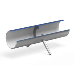
The EMCO Orifice Plate is used as a primary element in flow measurement of liquid, gas and steam applications based on the differential pressure principle. According to this working principle, the orifice plate creates a flow restriction in the pipeline to allow measurement of the resulting pressure drop and flow rate.

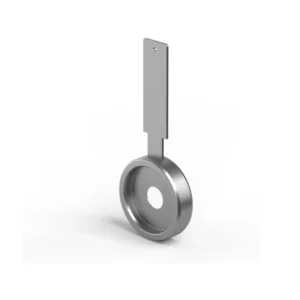
The Orifice Plate Series MEF is constructed with a single pressure tapping for insertion between flanges.

Download Documents

Design

Installation
Before installation, the orifice plate must be kept clean and protected against corrosion and physical damage. It is also important that you pay careful attention to to the sharp edge of the plate. Once ensured that it is clean, install the orifice plate carefully such that the orifice bore aligns with the centre of the pipeline. Tap location varies depending on whether it is used for liquid, gas or steam. It is not supplied with any safety devices and must not be used for higher pressure, than stated on the name plate. The pipe system must therefore be equipped with a safety device. However, this type of primary element requires no special maintenance.
  • Predictable pressure loss
  • Simple construction
  • Proven design
  • Cost-effective

Design and calculation standards

ISO 5167-2, ASME MFC-3M, DIN 19205, Shell Flow Meter Engineering Handbook, L. K. Spink, AGA no. 3

Sizes

DN 50 – 600, 2″ – 24″

Pressure rating

PN 10 – 40, 150 – 600 lbs

Plate thickness

3 – 8 mm

Vent or drain hole

On request

Material

AISI 316, other on request

Mounting style

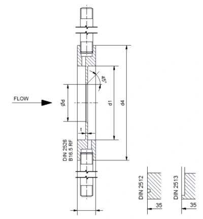
Between flanges with flat or raised face according to DIN 2526, 2513, 2512, EN 1092-1 or RF according to B 16.5

Pressure taps

3/8″, 1/2″ BSP male, Ø 12 mm, 1/2″ NPT

Tap Length

150 mm, others on request.

Tap Location

At least 45 degrees apart to be stated with order

Connection

Flanges with flat or raised face according to DIN 2526, 2513 or 2512, or RF according to ANSI B 16.5

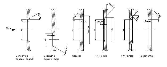
Orifice plate shapes

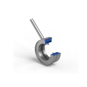
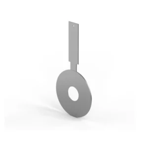
Square edge concentric as standard. See above illustrations for other shapes.

Marking

The orifice plate is marked with “+” and”-” and flow direction.

Technical Data

Accuracy

+/- 0,6 % for β < 0,6 and equal to β for β values above 0,6

Pressure loss

Depending on β, for β equal to 0,6 : ca. 60 % of the differential pressure measured

Limits for Reynolds No

Re > 1260 x β2 D according to ISO 5167 2000 < Re < 108 according to ASME MFC-3M

Accessories

Shut-off valves and condensing chambers for steam flow measurement. Flange assembly complete with bolts, nuts and gaskets

ต้องการใบเสนอราคา

Line add : @intech2000

Email : intech@intech2000.com

Phone : 02-440-1853

Scroll to Top