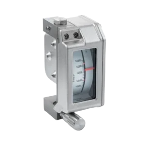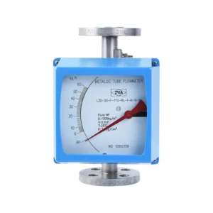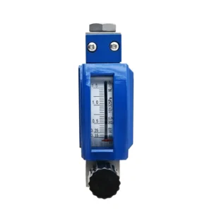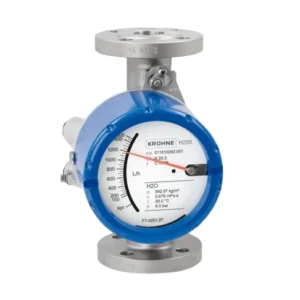
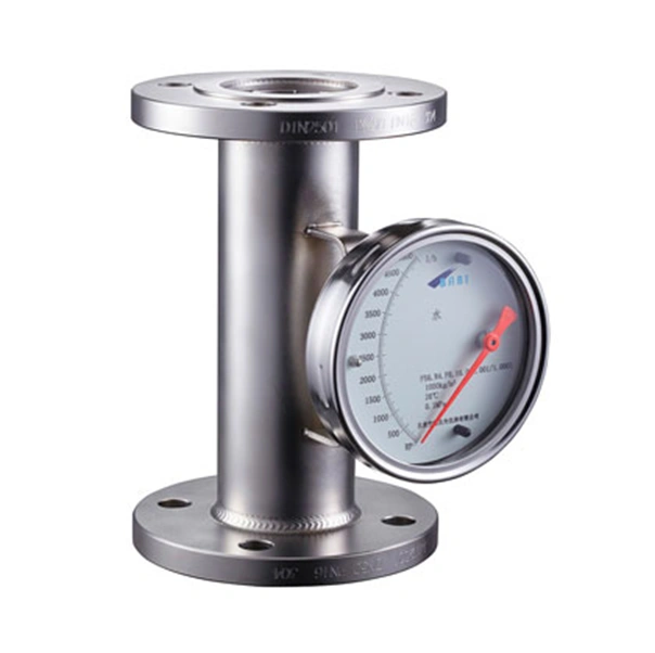
BABI F56/P8L Variable Flow Meter โรตามิเตอร์ท่อโลหะ พร้อม Mechanical Indicator สำหรับแสดงอัตราการไหล เหมาะสำหรับงานอุตสาหกรรม
- Designed for food industry.
- Easy to disassemble, clean and maintain.
- Housing made of stainless steel, corrosion resistant.
- Indicator made of stainless steel by stamping forming, surface polished, beautifuland compact structure.
- Local display indicator and local display with transmitter indicator are optional tomeet a variety of control requirements.
- Varieties of nominal diameter are available up to DIN3276(I SO2852, ASME andso on).\
- Standard clamp connection.
| Type | F56 | |||
| Medium | Liquids, gases, vapors | |||
| Rang(conversion to 100% value of reference fluid ) | Water : 20℃ | (10-300000)L/h , Special order on request: | ||
| Air : 0.1013MPa, 20℃ | (0.7-3000)Nm3/h, Special order on request: | |||
| The turn-down ratio | 10 : 1 | |||
| Accuracy class | Mechanical indicator | 1.0, 1.5, 2.0, 2.5 | ||
| Mechanical indicator with LCD(battery powered, service life: 2 years) | 1.0, 1.5, 2.0, 2.5 | |||
| Mechanical indicator with two-wire signal output (4-20)mA/hart communication protocol | 1.0, 1.5, 2.0, 2.5 | |||
| Medium temperature | Machinery indicator with LCD(battery powered, service life: 2 years) | -80℃~+300℃ (PTFE:0~80℃)
High temperature 400℃ |
||
| Mechanical indicator(battery powered, service life : 2 years) | -40℃~+120℃ (PTFE:0~80℃)
High temperature 400℃ |
|||
| Mechanical indicator with two-wire signal output (4-20)mA/hart communication protocol | -40℃~+120℃ (PTFE:0~80℃)
High temperature 400℃ |
|||
| Ambient temperature | Mechanical indicator | -40℃~+120℃ | ||
| Mechanical indicator with LCD(battery powered, service life: 2 years) | -20℃~+60℃ | |||
| Mechanical indicator with two-wire signal output (4-20)mA/hart communication | -20℃~+60℃ | |||
| Viscosity of fluid | DN15: F15.00~F15.03 η<5 mPa.s, F15.04~15.30 η<30 mPa.s; DN25: η<250 mPa.s; DN50~250: η<300 mPa.s | |||
| Nominal pressure | DN15~DN50 | 4.0MPa(Max DN15: 42MPa, DN25: 42MPa, DN50: 32MPa) | ||
| DN80~DN250 | 1.6MPa(Max DN80: 10MPa, DN100: 6.4MPa, DN125: 4.0MPa,
DN150: 4.0MPa, DN200: 2.5MPa, DN250: 2.5Mpa) |
|||
| Process connection | Flange connection, Standard: DIN2501, ANSI, JIS(select Chinese standard freely, priority select DIN) | |||
| Hygiene clamp, screw joint are selected in the order | ||||
| Electrical connection | M20×1.5 1/2″G 1/2″NPT 3/4″G 3/4″NPT | |||
| Installation | Vertical installataion(bottom in up out and up in bottom out, Horizontal installataion(left in right out and right in left out)
bottom in side out, side in side out |
|||
| Straight unimpeded inlet run | ≥ 5D | |||
| Straight unimpeded outlet run | ≥ 250 mm | |||
| Degree of protection | IP67(Others need specify in the order) | |||
| Ex marking | EEx ia II CT5 | |||
| EEx d II CT6 | ||||
| Ex electrical data | Ui = 28V Ii = 93mA Pi = 0.65W Ci ≤ 5nF Li =0mH | |||
| Safety barrier data | Uo ≤ 28V Io ≤ 93mA Po ≤ 0.65W Co ≥ Ci+Cc Lo ≥ Li+Lc | |||
| Carried Standard | JB/T 6844-93 | |||
ต้องการใบเสนอราคา